Chain dimension
![]()
This function allows you to create a series of linear dimensions spatially aligned.
The dimensions are automatically generated with:
- A parallel orientation in respect to the orientation of the first one and aligned at the level of its application point.
- The starting point coincident with the application point of the previous one.
![]() Note:
Note:
After initial selection, subsequent dimensions only require one point to be picked at each step.
Access
- In the Annotations tab, click the
 icon in the Ordinate section of the ribbon.
- Type Chain in the Quick Search field and select Chain dimension.
This opens the tab containing the Filters and Attributes sections.
Procedure
- Select the appropriate Filters options.
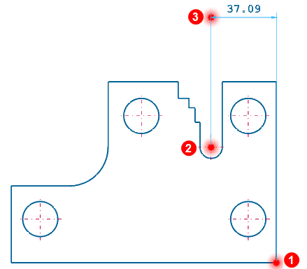
- Define the first reference dimension by selecting its extremities: example point
 and point
  .
. - Identify the application point of the first dimension: example point
 .
. - Select the X-axis or the Y-axis direction by dragging the zero point in the required direction or click the Direction
 icon to select a different direction by selecting an existing segment or line in the graphic area.
 - To load the Dimension Properties dialog by clicking on the Properties
 icon. This dialog can also be loaded by pressing the [T] Key to enter and configure text after validation.(See Chain Dimension Properties).
 -
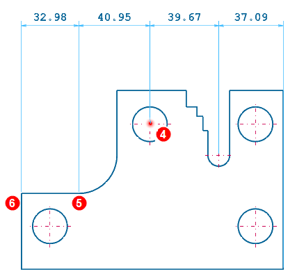
Continue to create as many Chain dimensions as you may need by sequentially selecting all the required points. From now onward it is possible to:
- Select multiple points having the same characteristics (defined through the Filters icons) for automatic dimensioning by activating the Into a windows
 icon and drawing a rectangle around the required area in the graphic area.
 - Define the new Dimension Properties ( Properties icon or [T] Key).
For example select the centre of the circle
 , the final point of the arc
  and the intersection point
  .
. Note:
Note:If you move the mouse back across an existing dimension, the values of the existing and of the new one will be modified according to the new application point.
- Select multiple points having the same characteristics (defined through the Filters icons) for automatic dimensioning by activating the Into a windows
- Once the last required dimension of the Chain has been identified, click the right mouse button or click on the Apply icon
 to validate and close the command.
![]() Note:
Note:
The position of the first dimension is displayed dynamically depending on the mouse position. Before validation, it is possible to perform the following operations from the General section of the Options tab:
Chain Dimension Properties
This dialog is loaded during the Chain dimensions creation, Chain dimension editing and Chain dimension/s adding.
General values Tab

|
Remember settings |
Activate this option to save your current settings. |
|
Text |
Enter the text string in this field. You can use keyboard shortcuts to add special characters:
|
|
Decimal places |
Enter the number of decimal places in this field. |
|
Text attribute |
Select the text attribute from the drop-down list: No Attribute, Underline, Overline, etc. |
|
Text colour |
Select the text colour. |
|
Tolerance colour |
Select the tolerance colour (See Tolerance Tab). |
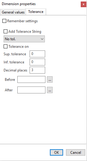
Tolerance Tab
|
Remember settings |
Activate this option to save your current settings. |
|
Add Tolerance String |
Activate this option to enable the drop down menu from which to select a predefined text to be added after the Chain dimension value: No Tol., (4 holes), (2 holes), Symm 0,05, etc.... |
|
Tolerance on |
Activate this option to display the tolerance values defined in the Sup. tolerance and Inf. Tolerance fields. |
|
Sup. tolerance |
Enter the upper limit value of the admitted tolerance range. This value displays after the dimension value. |
|
Inf. tolerance |
Enter the lower limit value of the of the admitted tolerance range. This value displays after the dimension value. |
|
Decimal places |
Enter the number of decimal places to display. |
|
Before |
Enter the text to be added before the dimension. This option allows you to select predefined text in the application:
|
|
After |
Enter the text to be added after the dimension. This option allows you to select predefined text in the application:
|
Chain Annotation Properties
This dialog is loaded during the Chain annotation editing: the edited properties apply at the whole set of dimensions.
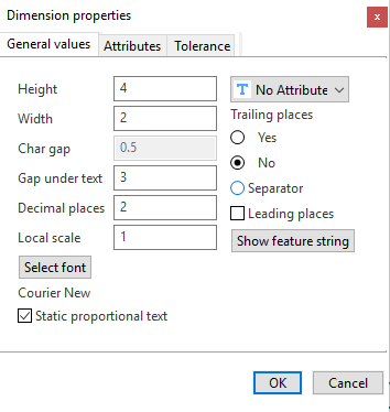
General values Tab
|
Height |
Enter the height of characters in this field. |
|
Width |
Enter the width of characters in this field (only for static text). It is disabled if the Static proportional text option is activated. |
|
Char gap |
Enter the distance between each character in this field. It is disabled if the Static proportional text option is activated. |
|
Gap under text |
Enter the distance between the text and the dimension line in this field. |
|
Decimal places |
Enter the number of decimal places to display. |
|
Local scale |
Enter a new text scale in this field. |
|
Select font |
Click this button to define the font parameters. |
|
Static proportional text |
When this option is activated, proportional text is applied; the width of characters is calculated as a ratio relative to the height of characters. |
|
Text attribute |
Select the text attribute in this drop-down list: Underline, Overline, etc. |
|
Trailing places |
Select whether you want to display (Yes) the insignificant zeros following the decimal places or not (No). |
|
Separator |
Activate this option to draw a point after the integer when there are no trailing places. |
|
Leading places |
Activate this option to display all of the insignificant zeros which precede the decimal place. |
|
Show feature string |
Click this button to display the CAM string defined inside the "Feature.cfg" file. |
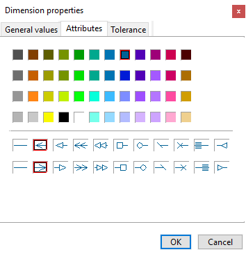
Attributes Tab
|
Text colour |
Select the text colour. |
|
Arrow Style |
Select the arrow style displayed at each extremity of the dimension line. |
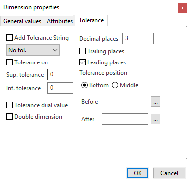
Tolerance Tab
|
Add Tolerance String |
Activate this option to display the tolerance settings. Select the tolerance settings from the drop-down list below the option. |
|
Tolerance on |
Activate this option to insert tolerance text after the dimension value. |
|
Sup. tolerance |
This field indicates the upper tolerance value. The value depends on the tolerance settings selected in the Add Tolerance String drop-down list. |
|
Inf. tolerance |
This field indicates the lower tolerance value. The value depends on the tolerance settings selected in the Add Tolerance String drop-down list. |
|
Tolerance dual value |
Activate this option to display the upper and lower tolerance values between brackets after the dimension value. |
|
Double dimension |
Activate this option to display the dimension value in both mm and inches. |
|
Decimal places |
Enter the number of decimal places in this field. |
|
Trailing places |
Activate this option to display the insignificant zeros following the decimal places. |
|
Leading places |
Activate this option to display all of the insignificant zeros which precede the decimal place. |
|
Tolerance position |
Select whether to position the upper and lower tolerance value level at the Bottom of the dimension value or in the Middle of the dimension value. |
|
Before |
Enter the text to be added before the dimension in this field. This option allows you to select predefined text in the application:
|
|
After |
Enter the text to be added after the dimension in this field. This option allows you to select predefined text in the application:
|
Editing existing Chain annotation
- See Edit dimension.